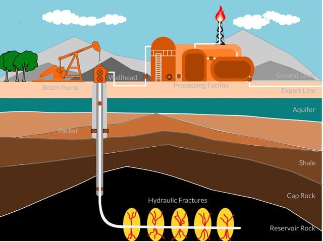
The wellhead is a critical component of an oil or gas well, and it serves as the interface between the wellbore and the surface equipment. It's located at the top of the well casing or tubing, and its primary functions are containment, control, and monitoring of fluids and pressures in the well. Here are the key elements and functions of a wellhead:
1. Pressure Containment: The wellhead provides a pressure-tight seal to prevent the escape of reservoir fluids (oil, gas, or water) from the wellbore. It contains the high pressures found deep within the well.
2. Connection Point: The wellhead serves as a connection point for various surface equipment, including production tubing, casing, control valves, and flowlines.
3. Control Valves: Control valves, such as chokes and safety valves, are often integrated into the wellhead to manage and control the flow of fluids from the well. These valves regulate pressure and flow rates.
4. Monitoring Points: Pressure and temperature sensors are typically installed on the wellhead to continuously monitor downhole conditions. This data is crucial for well control and optimization.
5. Safety Measures: Wellheads may include safety features like blowout preventers (BOPs) to prevent uncontrolled releases of hydrocarbons, especially during drilling, completion, and well testing operations.
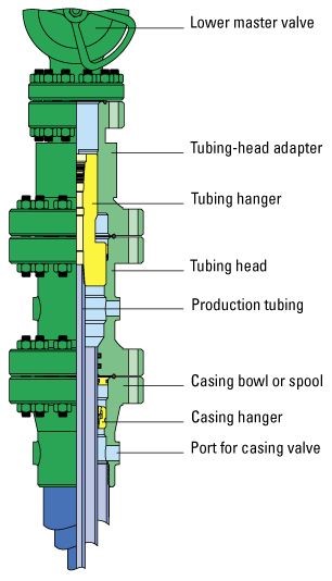
7. Tubing Hanger: In wells with tubing strings (common in production wells), a tubing hanger supports the tubing and provides a seal to prevent fluid escape.
8. Production Tree: In many cases, a production tree is installed on top of the wellhead. It's a set of valves and fittings used to control the flow of hydrocarbons from the well to the production facilities or pipelines.
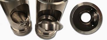
6. Casing Hanger: The casing hanger is a component of the wellhead that supports the casing and provides a seal between the casing and the wellhead. It helps maintain well integrity.
6. Casing Hanger: The casing hanger is a component of the wellhead that supports the casing and provides a seal between the casing and the wellhead. It helps maintain well integrity.
9. Fluid Separation: In some wells, particularly those producing water along with oil and gas, a separation system may be integrated into the wellhead to separate and collect different phases (oil, gas, water) before they are transported.
Wellheads are designed to withstand high pressures, corrosive environments, and extreme temperatures. They are a crucial part of ensuring safe and efficient oil and gas production operations. The specific design and components of a wellhead can vary depending on the well's purpose, depth, and the characteristics of the reservoir.
read more....
What are the types of x-mas trees?
a production tree, also known as a Christmas tree, is an assembly of valves, spools,
and fittings used for controlling the flow of oil or gas from a well. The type of production tree
used depends on factors such as well conditions, production requirements, and safety considerations.
Here are some common types of production trees:
Conventional Christmas Tree: This is a standard configuration used for most conventional wells. It includes valves for controlling the flow of oil or gas, as well as other components such as a choke, master valve, wing valve, and pressure gauges.
Dual Tubing Christmas Tree: In wells with dual tubing strings (two separate tubing strings for production), a dual tubing Christmas tree is used. It allows for independent control of each tubing string.
Through Tubing Christmas Tree: This type of tree is designed to accommodate through-tubing operations, where tools or instruments are run through the tubing string without the need to pull the tubing.
Horizontal Christmas Tree: For wells with horizontal completions, a horizontal Christmas tree is used. It is designed to handle the challenges posed by horizontal wells, such as controlling flow from multiple zones.
Dual Completion Christmas Tree: In wells with multiple reservoirs, a dual completion Christmas tree is employed. It allows for the independent control of each completion zone.
Vertical Subsea Christmas Tree: Subsea Christmas trees are installed on the seafloor for offshore wells. A vertical subsea tree is suitable for vertical well completions.
Horizontal Subsea Christmas Tree: This type is designed for subsea completions in horizontal wells. It provides the necessary control for horizontal well configurations.
ESP (Electric Submersible Pump) Christmas Tree: In wells that use electric submersible pumps for artificial lift, a specialized ESP Christmas tree is used to accommodate the pump and control its operation.
Slimhole Christmas Tree: Slimhole trees are designed for wells with smaller diameters. They are often used in slimhole drilling and completion operations.
Smart Christmas Tree: Some modern trees are equipped with smart technologies, such as sensors and communication systems, to enable real-time monitoring and control of well parameters.
The selection of the production tree depends on the well's characteristics, the type of reservoir,
and the production strategy. Each type of tree is designed to meet specific operational requirements
and ensure the safe and efficient production of hydrocarbons from the well.
read more....
What are types of downhole vlaves?
DHSV:D:own
H:ole
S:afety
V:alve
TRSVTubing
Retrievable
Safety
Valve
DHIV:Down
Hole
Injectivity
Valve
The selection of the production tree depends on the well's characteristics, the type of reservoir,
and the production strategy. Each type of tree is designed to meet specific operational requirements
and ensure the safe and efficient production of hydrocarbons from the well.
read more....
Flowhead
Flowhead is a temporary Christmas tree, it is located on top of the well, it it the first piece of equipment at the surface that fluids flow through.
flowhead applications:-
pre-completion testing
Drill Stem Testing
post-completion testing
flowhead features and benefits:-
that allows isolation of the surface equipment from the downhole test string.
Swab valve:that permits introduction and retrieval of wireline and slickline tools.
flowline valve:allows fluid to flow from the well. this valve is usaully operated by hydraulic actuator for ESD.
kill line valve:used to pump fluid into the well -pumping acid to clean the wellbore and to increase porosity and permeability of the formation-
swivel:allows the test string suspendend from the flowhwad to be rotated independently of the main flowhead block.
elevator sub:used to handle the flowhead with the rig elevator
threaded connection:is located on top of the elevator sub which is used to attach pressure equipment.
read more....
Tower
on the tower we have:-
suddle tank =>is a container contains hydraulic oil for coolling the lines.
Riser =>
Scrubber =>
panel =>
read more....
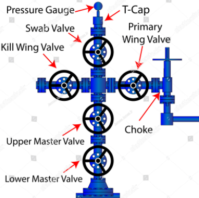
Christmas tree (X-mas tree/surface tree / production tree)
Lower master valve
Upper master valve
Swab valve
Tree cap
Kill wing / testing wing
Production wing
Manual wing valve
Hydraulic wing valve
Choke for production
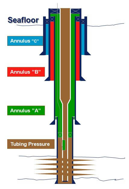
Annulus A (9 5/8)
Annulus B (13 3/8)
Annulus C
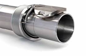
Clamp
read more....
New
Coming Soon
read more....
The Sealer
First it is drilled for the sealer ( that big hole box) it also prevent or save the well from any eruption or rocks to fall down in the well production casing while coil tubing or slick line are working
read more....
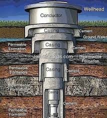
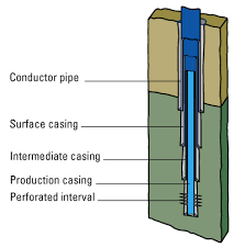
The Conductor
Second we drill in the ground and
we put the Conductor conductor by hammering it until refusal point
( when we hammer on the conductor 160 times and it moves only one feet).
We pump cement to put it between the conductor and the mud to be fixed
(not necessary)
read more....
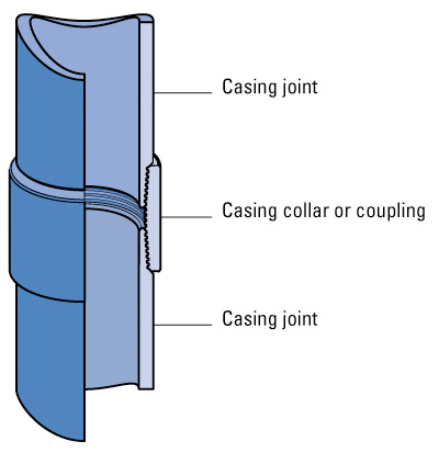
Collar or coupling
That pipes in the conductor jointed together with a threatening pipe
called collar or coupling
read more....
Surface casing
We put another pipe inside the conductor its name is surface casing
We repeat the cement process against to fix the casing pipe too
read more....
Intermediate casing
Then we put the Intermediate casing and the cement also
read more....
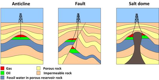
The reservoir
That hole that contain the fluids
read more....
Production tubing
Then we put a tube inside the Intermediate casing
going to the liner linear is the distance between
the end of that tube going to the reservoir
read more....
Linear
The packer is put between the tube and the intermediate casing
to fix the tube, to isolate between annulus and mud downside
and to pump the brine to equal the pressure outside the tube
and inside the tube with the oil
read more....
Brine/Erine liquid
we pump Brine to the water in the annulus to prevent the casing
from corrosion and the pressure of the annulus should be 0 and 200 maximum.
read more....
Flabber or the dowmhole
Flabber is put in the tube near the surface for emergency
shutdown and it works with the pressure we put from the downhole
to open it and it shut with the pressure of the oil flow
read more....
Annulus
The annulus is the gap between the tube and the Intermediate casing
and production tubing from it We pump the Brine and we can make bleed off
from that annulus
There are three annulus A 9 5/8, B 13 3/8, and C
read more....
Tubing spool
Tubing spool is the manifold of valves use to pump brine gas in the gap between the tube and the intermediate casing ( the annulus)
Hanger is the space in the linear like tubing Hanger
There is a crossover between the Christmas tree and the well head
Well head is the name of the distance and group of equipments including the tubing spool and casing spool
X-mas tree looks like the plus ➕
- From the up there are Swab valve and tree cap
- from the right the killing wing there are manual wing and Hydraulic valve
- from the left the production wing there are manual, and Hydraulic valve
Hydraulic valve works with the pressure of the the hydrolic oil that panel pump which works with air.
- from the down there are manual master valve and Hydrolic master valve
Formation is the mud and stones
Connect or Nipple up the BOP ( blow out preventer) to the intermediate casing by using an adapter and a casing head or a drilling spool
Double isolation is two closed valves [two bariers]
read more....
Production casing
There is a production casing which I think it's same as tubing and the final pipe going down inside intermediate casing
A liner is a shortened string of casing used to case the small open hole section below an existing casing string in a hole
it's just like casing except that a liner doesn't run all the way to the surface .
Instead the casing crew hangs it from the bottom of a previously run casing or
liner string using a special piece of equipment called liner Hanger it is used to save money
read more....
Clamp
It should be between annulus A valve and annulus B valve
read more....
Guide shoe
The guide shoe is a a heavy steel and concrete fitting
but the crew makes up in the end of the first casing
joint to go in the hole, it guides the casing rough spots
and ledges in the wellbore. It also has an opening and the end.
Drilling mud enters this opening when crew runs casing into
that wellbore - later cement will come out from
this opening on its way into the annulus
read more....
Float shoe
Maybe we substitute collar or the coupling with float shoe .
Centralizing
Scratcher
The cement main Job to completely isolate or totally seal off all the oil, gas and water
zones from the wellbore and to bond the casing firmly to the wall of the hall
The guide shoe and float collar
Cement head also called a plug retainer
Wiper plug is hanged with the cement head
read more....
New
The wellhead is a critical component of an oil or gas well, and it serves as the interface between the wellbore and the surface equipment.
It's located at the top of the well casing or tubing, and its primary functions are containment, control, and monitoring of fluids and pressures in the well.
Here are the key elements and functions of a wellhead:
1. Pressure Containment: The wellhead provides a pressure-tight seal to prevent the escape of reservoir fluids (oil, gas, or water) from the wellbore. It contains the high pressures found deep within the well.
2. Connection Point: The wellhead serves as a connection point for various surface equipment, including production tubing, casing, control valves, and flowlines.
3. Control Valves: Control valves, such as chokes and safety valves, are often integrated into the wellhead to manage and control the flow of fluids from the well. These valves regulate pressure and flow rates.
4. Monitoring Points: Pressure and temperature sensors are typically installed on the wellhead to continuously monitor downhole conditions. This data is crucial for well control and optimization.
5. Safety Measures: Wellheads may include safety features like blowout preventers (BOPs) to prevent uncontrolled releases of hydrocarbons, especially during drilling, completion, and well testing operations.
6. Casing Hanger: The casing hanger is a component of the wellhead that supports the casing and provides a seal between the casing and the wellhead. It helps maintain well integrity.
7. Tubing Hanger: In wells with tubing strings (common in production wells), a tubing hanger supports the tubing and provides a seal to prevent fluid escape.
8. Production Tree: In many cases, a production tree is installed on top of the wellhead. It's a set of valves and fittings used to control the flow of hydrocarbons from the well to the production facilities or pipelines.
9. Fluid Separation: In some wells, particularly those producing water along with oil and gas, a separation system may be integrated into the wellhead to separate and collect different phases (oil, gas, water) before they are transported.
read more....
what are types of downhole vlaves?
DHSV:>Down
Hole
Safety
Valve
TRSV: Tubing
Retrievable
Safety
Valve
read more....
Introduction to Drilling Engineering
Watch video
read more....
New
Coming Soon
read more....
Triplex Pump
Function
High-pressure pumping (used for injecting fluids, cleaning stimulation)
Specs
3 plungers, handles pressures up to 15,000 psi.
Examples of uses
pressure testing, acid jobs, water injection
read more....
Centrifugal Pump
Function
Fluid transfer and circulation at low to medium pressure
Specs
High flow rate, lower pressure than Triplex
Examples of uses
Transfer Oil, water or flowback fluid between tanks
read more....
Diaohragm Pump
Function
Low-Flow, chemical injection or small volume fluid transfer
Specs & features
Good for Corrosive or abrasive fluids
Examples of uses
small-scale chemical handling
read more....
Hydraulic Pump
Function
Effect
Specs
Odor threshold (rotten egg smell) H2S can be smelled
Examples of uses
Odor threshold (rotten egg smell) H2S can be smelled
read more....
Triplex Pump
Function
Effect
Specs
Odor threshold (rotten egg smell) H2S can be smelled
Examples of uses
Odor threshold (rotten egg smell) H2S can be smelled
read more....
New
Coming Soon
read more....
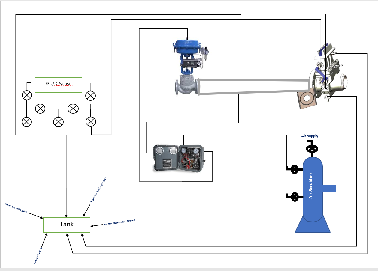
tools
How to dumb tank , separator and flush the line
to bleed oil in the Tank
prepare the pump
prepare the burner
pressurize the tank with (40-60) psi we can that pressure from the separator through pipe or through bleeder of the daniel or bleeder of the choke
start pumping oil to the sealine
take care of the air lock
dumbing water in the tank
line up from tank to overboard
you can pressurize the tank with afew gas to push the water
always check the return overboard
bleed and dumb separator
close the pcv to keep good pressure inside separator to push the level
open 3" oil line
you can open LCV full
flush the line
line up from pumping to our line until sealine
start flush and check the return always
once the return is clear water stop flushing and secure the line
read more....
New
Coming Soon
read more....
strainer
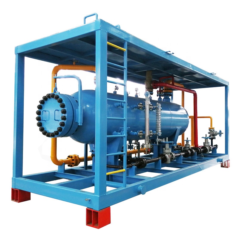
The Separator
The gas line :-
To increase or decrease the orifice (run the orifice) you need to do the following
1/ open the equalizer and open the gate then adjust from the carrier to make it in the upper chamber or down chamber finally open the upper chamber valve then close all previous valves inverse gate valve and equalizer.
Gas line can go to the production line and go for burner line by a diverter in the gas line in the Separator
The oil line:-
I can adjust the level from the lcv box to make the level stable and control form the pcv only
The Separator can be three phases
(water, oil and water) or two phases (liquid and gas)
read more....
Why do we have two different sizes of gas lines?
For low flow rate it is only suitable to use the smaller line
because the bigger line of PCV will not be able to maintain a stable pressure inside separator.
For high flow rate it is only suitable to use the bigger line
because if you flow through the smaller line would get turbulent flow which would give inaccurate flow measurement.
read more....
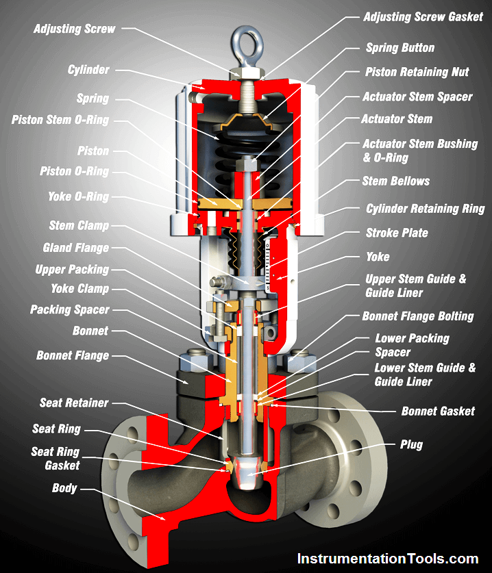
What type of valves do we use in lcvs and pcvs?
Throttling valves.
read more....
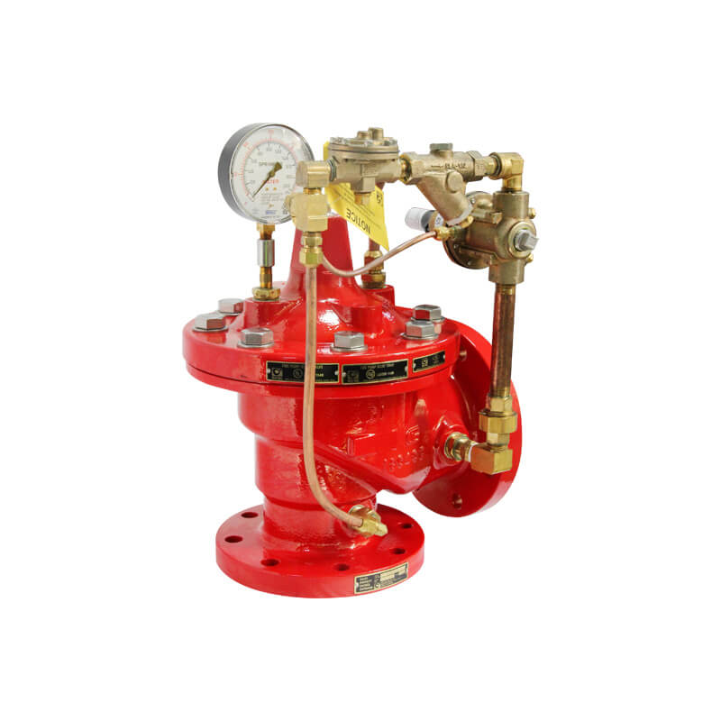
What is the pressure setting for the relief valve on separator and surge tank?
For separator the pressure setting of the relief valves are 100% and 105%. For surge tanks
the pressure setting of the relief valve is 100%.
read more....
diagram of gas tubes
Check the Layout
read more....
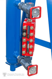
What is the sight glass types?
Transparent, refractive and magnetic
read more....
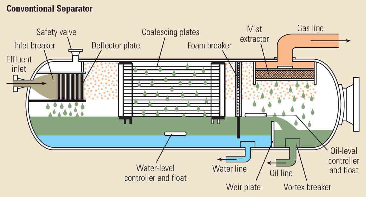
Explain separator inner parts.
Deflector plates (Inlet configuration):
This plate is located in the front of the inlet it causes a rapid change in direction
and velocity of the fluids, forcing the liquid to fall to bottom of the vessel.
The deflector plate is responsible for the initial gross separation of liquid and gas.
Coalescing plates (Intermediate Configuration):
These plates are arranged longitudinally in an invert V-shape in the upper part of the separator,
the liquid droplet in the gas hit the plates and stick to them,
as more gas through the plates, more droplets coalesce to form bigger drops that fall to bottom of the vessel.
Weir plate (Intermediate Configuration):
This plate located at the bottom of the separator, divided the separator into two compartments
(Oil and Water) provided that the water level is controlled,
it only permits oil to overflow into the oil compartment.
Foam breaker (Intermediate Configuration):
This piece of equipment is made of wire mesh, like the mist extractor.
It prevents oil particles in the foam (comprised of oil and gas)
from passing through the separator and being carried away with the gas.
Mist extractor (Outlet configuration):
This piece of equipment is composed of a mass of wire netting.
Before leaving the separator, the gas stream passes through the mist extractor,
causing the tiny oil droplets remaining in the gas to fall down.
Vortex breaker (Outlet configuration):
These breakers are located on the oil and water outlets.
their function is to break the vortex effect that can occur when oil and water exit the separator
from their respective outlets. the vortex breakers prevent any gas from being sucked away with the liquids.
read more....
What is the difference between junior and senior Daniel?
For Junior Daniel
It has a single chamber which makes it impossible to change the orifice size
when you are flowing through gas line without stopping the operation.
For senior Daniel
it has two chambers which makes possible to change the orifice plate without interrupting
the operation.
read more....
What is the meter factor?
The ratio between the tank volume/reading divided by the meter reading.
read more....
What are the flow meter ranges?
For 1 inch 170-1700 or 1300 bbl/day
For 2 inch 1300-13000 bbly/day
read more....
What are straightening vanes?
They are a number of tubes placed in the gas line to streamline the flow
before it enters the Daniel box in order to obtain laminar flow to be able to measure the gas rate.
read more....
New
Coming Soon
read more....
How to change orifice plate
open the differential equalizer
open the equalizer valve
open the gate valve
make the plate up
close the gate valve
close the equalizer
bleed the uppr chamber
get the orifice plate out of the daniel boxand change it
read more....
How to Run orifice plate
after putting the orifice plate
close the upper chamber bleeder
open the equalizer
open the gate valve
make the plate down
close the gate
close the equalizer
close the differential equalizer
check the differential sensor readings
start flow test
read more....
What is the different between 3" & 6" gas line
comparion
3" gas line
6" gas line
the ID
2.901"
5.772"
back pressure
high
low
read more....
How to change between 3" & 6" gas line in fekete?
Coming Soon
read more....
How to dumb tank , separator and flush the line
to bleed oil in the Tank
prepare the pump
prepare the burner
pressurize the tank with (40-60) psi we can get that pressure from the separator through pipe or through bleeder of the daniel or bleeder of the choke
start pumping oil to the sealine
take care of the air lock
dumbing water in the tank
line up from tank to overboard
you can pressurize the tank with afew gas to push the water
always check the return overboard
bleed and dumb separator
close the pcv to keep good pressure inside separator to push the level
open 3" oil line
you can open LCV full
urn the remaining gas in the separator
flush the line
line up from pumping to our line until sealine
start flush and check the return always
once the return is clear water stop flushing and secure the line
read more....
New
Coming Soon
read more....
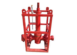
rock catcher
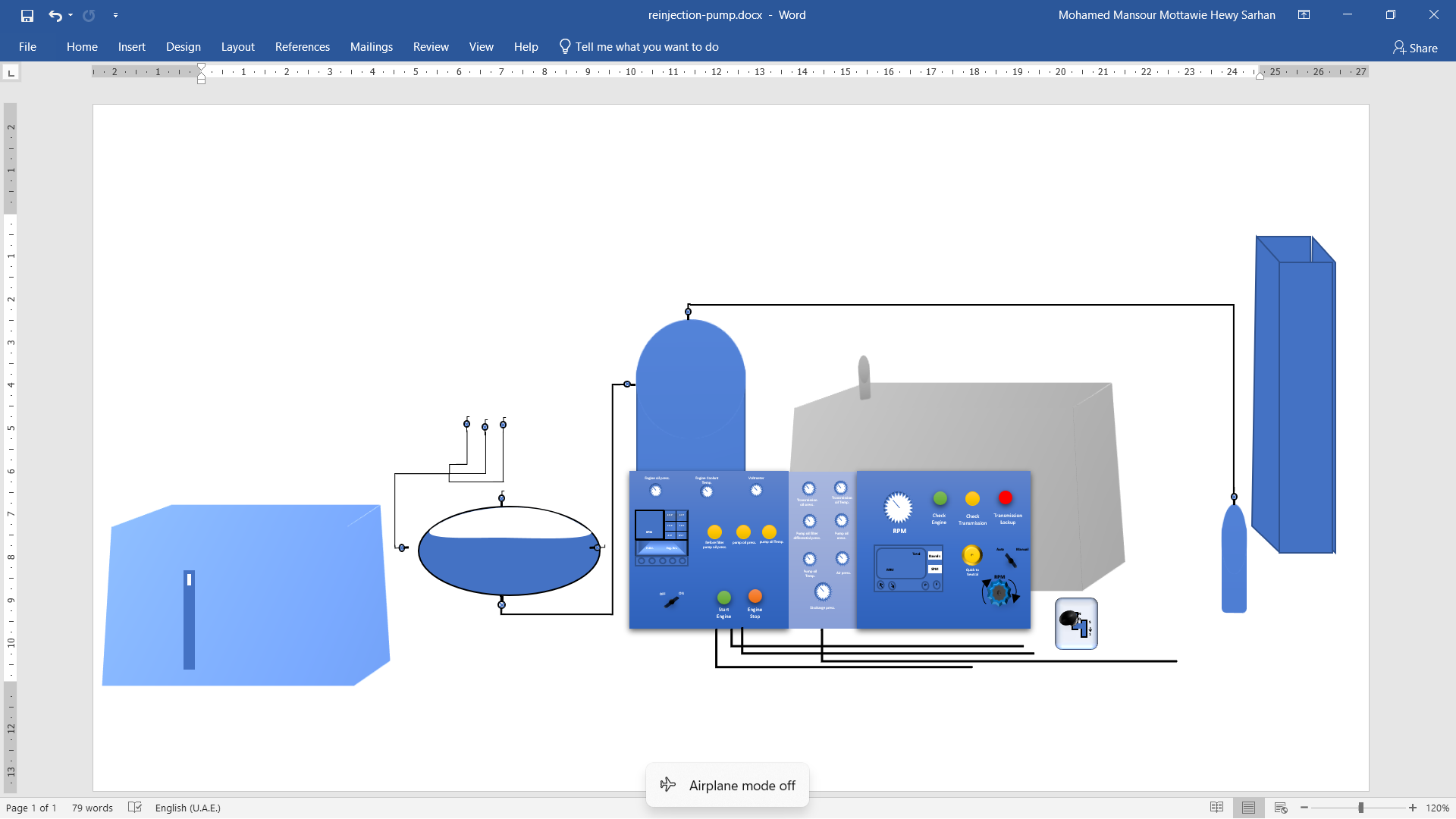
reinjection pump
The reinjection pump is gear
the procedures to run this pump:-
open the air hose from the surge tank ait scrubber to the pump crack open and take care of panel air supply
turn on the key in its panel
instead of pushing the green button, just open the pump scrubber air valve to run it and close it again
open the scrubber air valve going to the hydraulic oil container
open the valve on the inlet air hose to the hydraulic oil container
crack open the three valves of the hydraulic oil container outlet
with pressing the button on the stick, turn the Drive stick from (N) neutralized down and right to put it on number 1,2,3,4 or 5
use the RPM Gear to increase the rate
every 15 minutes poor two drops of hydraulic oil
check the level of the disiel
check the level of the engine oil
read more....
reinjection pump
Types oF container we need to fill
Engine Oil (HYDRAULIC OIL 100)
Hydrolic oil
Diesel
coolant water
read more....
Diaphragm
In the pump we have a plunger and suction
Plunger can be four and half
Or it can be three and half
Four and have used for high rate low pressure
Three and half used for low rate high pressure
Plunger us using hydrolic oil (lubricant oil) or it can use Geer oil also for transmission
Suction is positioned in the bottom of the engine of the pump
Plunger is positioned in the top of the engine of the pump below the three needle valves of hydrolic oil
read more....
New
Coming Soon
read more....
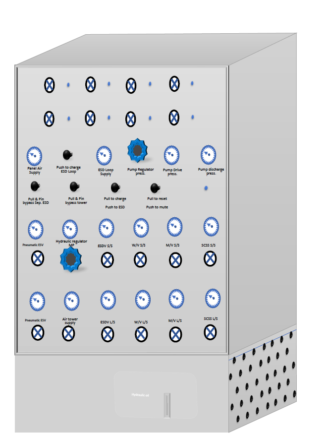
Diagram of the panel
How to charge the panel?
pull to charge ESD
pull & pin bypass Sep. ESD
pull & bypass tower
How to Shut-in the panel?
push for ESD
read more....
panel
Close the outside valve to isolate the line
close half of the valve to isolate
open the valve full open to start pumping
push to charge ESD Loop supply
check the panel air supply
read more....
New
Coming Soon
read more....
Eruption
Generator
Filter unit
New
In the context of well testing,
"ESD" commonly refers to "Emergency ShutDown" or "Emergency Shut-In."
This term is related to safety measures and protocols in the oil and gas industry,
particularly when conducting well testing operations.
An Emergency ShutDown (ESD) system is designed to rapidly and automatically shut down
or isolate a well or a facility in the event of an emergency.
The purpose of an ESD is to mitigate risks, protect personnel,
and prevent or minimize damage to equipment and the environment.
During well testing, various factors such as high pressures,
unexpected flow conditions, equipment malfunctions,
or safety breaches could pose a risk.
In such situations, the ESD system can be activated to quickly close valves,
isolate the well, and bring the entire system to a safe and controlled state.
Key components of an ESD system in well testing may include:
Emergency Shutdown Valves (ESVs):
These are valves that can be automatically or manually closed to stop the flow of fluids in the event of an emergency.
Control Systems:
Automated control systems are used to monitor key parameters such as pressure,
flow rates, and temperatures.
If any parameter exceeds predefined safety limits,
the control system triggers the ESD.
Safety Instrumented Systems (SIS):
These are systems designed to ensure the safe operation of a process or facility.
They include sensors, logic solvers, and final elements (such as valves) that actuate in response to predetermined conditions.
Emergency Response Procedures:
Well testing operations have well-defined emergency response procedures that guide operators on
how to handle emergency situations, including when and how to activate the ESD system.
read more....
Emergency Shutdown (ESD) valves
Emergency Shutdown (ESD) valves are critical components in safety systems,
especially in the oil and gas industry.
They are designed to quickly close and isolate a process or equipment in emergency situations
to prevent accidents or protect personnel and assets.
Various types of ESD valves exist,
and the selection depends on factors such as the application,
fluid type, and system requirements.
Here are some common types of ESD valves:
Ball Valves: have a rotating ball with a bore through it.
In the closed position, the ball blocks the flow path, providing a quick shut-off.
Ball valves are often used for ESD applications due to their fast-acting nature.
Gate Valves: use a gate (usually a flat or wedge-shaped disc)
to block the flow. They are suitable for applications where a tight seal is required.
Gate valves may have rising or non-rising stems.
Butterfly Valves: have a disc that pivots on a central shaft
to control the flow. In an emergency, the disc can be quickly rotated to the closed position.
Butterfly valves are known for their quick operation.
Piston Check Valves: Piston check valves use a piston-like disc
to control the flow. In an emergency, the piston is forced into the closed position,
preventing backflow.
read more....
New
hydraulic Valves an actuator on the flow head or a surface safety valve independent on the flowline
high/low pilot
stations
ESD panel which is composed of :--
hydraulic pump
hydraulic oil tank
air vessel
interface valve
check valve
quick exhaust valve
reset valve
by-pass valve
ESD pilots should be located on
flowline
data header
test separator
steam exchanger
to control vessel pressure if the pressure is increasing it should be activated.
read more....
New
Coming Soon
read more....
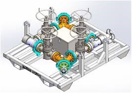
Choke manifold compotents
It controls the flow rate and the pressure of the well head
It's located downstream of the flow head
The maximum size is 128 which it equals two inches
Adjustable choke and fixed choke
read more....
why the adjusable choke on the right side of the chokemanifold ?
The Adjustable choke is in the right side for emergency
if something happen we can easily close it in the same direction of the flow
to be easy to close.
To maintain the direction of flow
to be the same of closing direction of adjustable choke.
read more....
chokemanifold features:-
chokemanifold is used to control the fluid from the well by reducing the flow pressure
and by achieving a constant flow rate before the fluid enter the processing equipment on the surface.
Four gate valves
a posititve or fixed choke.
Tapping points for measurements of the upstream and downstream pressure
Thermometric well to monitor the temprature of the well
An adjustable choke
read more....
changing from the adjustable to fixed choke
preparation of fixed choke
adjust the adjustable choke until the flow stabilizes, then prepare the equivalent fixed choke to be installed
pessurizing fixed choke box
open the downstream valve of the fixed choke box to equalize the pressure (it is advisable to open the downstream rather than the upstream for safety measure)
Diverting the flow from adjustable to fixed choke
open simultaneously upstream valve on the fixed side wile the upstream valve of the adjustable side is closed
flow through fixed choke
the downstream of the adjustable side is closed in pressure bled off on the adjustable choke.
read more....
chokemanifold principle functions
safety function by controlling the well head pressure
it allows different choke sizes to control the flow rate
it prevents wate and gas coming by limiting the flowrate
it prevents formation sabd from entering the well by limiting the flow rate
it ensures critical flow where the pressure fluctuations downstream of the chokemanifold do not affect downhole pressure and flowrate of the well.
read more....
chokemanifold types according to:-
working pressure (5kpsi, 10kpsi, 15kpsi)
types of gate valves (McEvoy, Marbranque, Sereg, and WOM)
read more....
The procedures to change from adjustable choke to fixed choke :-
bleeding the fixed choke between upstream and downstream valves to the tank
prepare the choke bean size
open the fixed choke valve
get the choke bean out and put the new one
close the fixed choke cover
do a function test for the bleeder valve by opening the downstream fixed choke valve
open the upstream fixed choke and close the upstream fixed choke simultaneously
close the downstream adjustable choke
read more....
why the low pilot is upstream of the choke and high pilot is downstream of the choke :-
low pilot is upstream of the choke manifold
becuase if the upstream pressure going down that means that mayebe there is a leak in the upstream line or in the xmass tree we need to fix
high pilot is downstream of the choke manifold
because if the downstream pressure doing up more than the pressure of the high pilot predefined on so the line will shutdown to protect our equipment as a safety meassures
read more....
New
Coming Soon
read more....
New
Coming Soon
read more....
New
Coming Soon
read more....
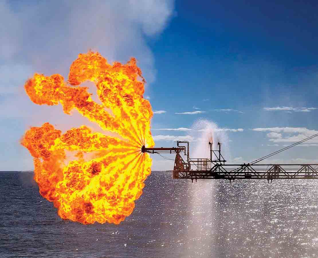
Burners
Burners are used to dispose the oil at the surface during a well test
therefore avoid oil storage and pollution.
it limit heat radiation on rigs
by installing them on long booms that keep them at a safe distance from the rig.
read more....
Burners principles & Needs:-
Atomization of well effluent result in reduction in fine droplets.
propane for pilots
Electricity for lodge box
Air compressors
Water to prevent heat radiation
read more....
Burner features:-
water ring for better CombustionHearth to guide the Airpilot light
located below the atomizer
small propane burner with spark plug.
lit by sending high voltage from a remote control box (lodge box)
Ball valves to select number of heads.air and oil check valves to prevent air to pass to oil line and vice versa.
never use rig air supply, always use dedicated air compressors(usualy two)
a check valve is mounted on the upstream atomizor of the air line to prevent oil to go to compressor's engine.
A check valve is mounted on the oil line to prevent the air from entering the atomizer into the oil line.
swivel joint
act as pivot to support the whole burner
allow to the burner to br positioned up to 75 degrees
read more....
Booms
the burner is mounted on a boom to keep it away from the rig to reduce heat radiation
heat radiation is also controlled with curtains of water on boom.
the boom provides (gas flare pipe - and piping to supply air, water, oil and propane)
the booms are usually installed in opposite sides (port side and star port side) od the drilling rig for safe burning in changing winds.
Length: 60ft or 85ft
Structure: V shape or U shape
Equipments
king post
base plate
horizontal guy lines
Vertical guy lines
Booms mounted on the rig with a rotation base plate to allow horizontal and vertical movements
horizontal guy lines are used to orient the boom horizontally
vertical guy lines, fixed to the king post or rig structure, support the boom
read more....
What should be the distance between green burner and propane?
At least 600 feet.
read more....
New
check the wind direction to the port or star port side
make sure that the wind speed between 5knots and 30knots
take the permission from the admin to flare
tell the engine room to open the coolling system
connect the ignition socket to Electricity
line up the propane cylinder to the burner
press the ignition green button to ignite the burner
line up the Equipments to the burner
while flaring ckeck always that there is no oil droping in the sea